Frameless BLDC Joint Motor for Robotic Arms
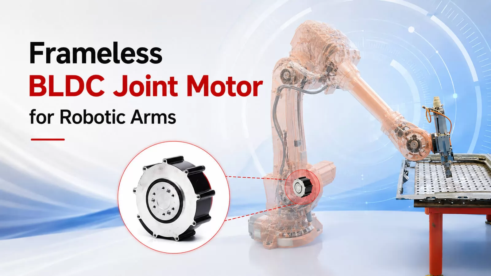
Why the Industry Moved to Frameless — and Why It Is Not Going Back
Five years ago, most cobot designs still bolted a housed servo motor onto a joint bracket and coupled it to a harmonic drive through a flexible shaft coupler. It worked. It also meant three sets of bearings stacking tolerances into the final joint precision — the motor's bearings, the gearbox's input bearings, and the joint structure's bearings. Every interface added backlash, weight, and a thermal resistance layer between the windings and the outside world.
Frameless construction eliminates all of that. You bond the stator directly into the joint housing, press the rotor onto the joint output shaft, and let a single cross-roller bearing handle every load the joint will ever see. The result is a joint that is 30–40% lighter at the same torque, routes cables through a hollow center bore, and — critically — has a cleaner torque-current relationship because there is no parasitic friction from redundant bearing sets.
This is not a theoretical advantage. It is the architecture inside Universal Robots' UR series, Franka Emika's Panda, and every humanoid arm program that has reached hardware prototype: Tesla Optimus, Figure 02, Apptronik Apollo. The technical debate about whether to use frameless for precision robotic joints ended around 2021. The remaining question is which frameless motor, from which supplier, with what level of engineering support.
What Toosyn Brings to the Table
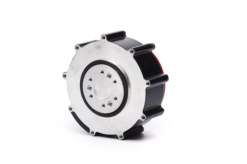
We manufacture frameless BLDC motors for robotic arm joints and humanoid actuators. Not general-purpose frameless motors that happen to fit into joints - motors designed from the magnetic circuit outward for the torque profiles, thermal duty cycles, and integration constraints of articulated robotics.
Three things define our technical position. None of them are marketing language; all of them are verifiable in our engineering samples.
Low-Cogging Magnetic Design
Cogging torque is the periodic torque ripple your controller sees even at zero current command. It comes from the magnetic interaction between the rotor's permanent magnets and the stator's slotted iron structure. In a position-only robot, cogging is a nuisance. In a force-controlled robot — any cobot, any humanoid, any surgical system — cogging is the enemy, because it introduces a high-frequency disturbance that the impedance controller must suppress.
Our target: cogging torque below 0.3% of rated torque.
How we get there is a combination of techniques that reinforce each other rather than relying on any single trick:
- Fractional-slot concentrated windings - our arm-joint platforms typically use 22-pole / 24-slot or 20-pole / 24-slot configurations. These fractional combinations distribute the magnetic interaction across more positions per revolution, spreading the cogging energy into higher harmonics that are easier for the controller to reject.
- Skewed stator slots - a helical skew along the stack length averages out the cogging over one slot pitch. The penalty is a small reduction in back-EMF (typically 2–3%), which we account for in the winding design.
- Magnet shaping - we use bread-loaf or sinusoidal magnetization profiles rather than simple radial arcs. This rounds off the flux density transitions at the magnet edges, which is where most of the cogging energy originates.
The practical test: when you run your FOC loop on a Toosyn frameless motor and plot the torque output against command, you should see a clean linear relationship without the periodic ripple that forces you to add aggressive low-pass filtering. If you have worked with cheaper frameless motors before and had to tune out a 6× or 12× per-revolution disturbance, that is exactly the problem this design eliminates.
Torque Density Within Real Joint Envelopes
Motor catalogs love to quote torque density in Nm/kg. That number is useful for comparing motors in the abstract. It is much less useful when your joint housing has a fixed outer diameter, a fixed axial length, and a hollow bore requirement that is non-negotiable because your cable bundle needs to pass through.
We optimize for a different metric: maximum continuous torque within a given cylindrical envelope, at a thermal steady-state that assumes realistic conduction into an aluminum joint housing — not into a laboratory heat sink with forced-air cooling.
Here is where our standard platforms sit relative to typical joint positions:
| Joint Position | Typical Motor OD | Continuous Torque Range (after harmonic reduction) |
|---|---|---|
| Base / Shoulder | 80–120 mm | 80–250 Nm |
| Elbow | 60–90 mm | 40–120 Nm |
| Wrist 1 (forearm rotation) | 50–70 mm | 15–50 Nm |
| Wrist 2 / Wrist 3 | 40–60 mm | 5–30 Nm |
If your joint does not fit neatly into these categories — and humanoid designs frequently do not — we have done custom dimensions for thin-profile forearm wrist drives, oversized shoulder yaw motors, and compact finger actuators. Custom geometry is engineering work, not a surcharge on a catalog part.
IATF 16949: What It Actually Means for Your Supply Chain
We are IATF 16949 certified. If you are building a research prototype, this does not matter to you — any competent motor manufacturer can ship samples that work.
If you are building a production robot that will ship in the hundreds or thousands, it matters a great deal. Here is what IATF 16949 specifically guarantees that ISO 9001 does not:
- Lot traceability from the raw NdFeB magnet blanks through magnetization, bonding, winding, and final test. If a motor fails in the field, we can trace it back to the specific magnet lot, the specific winding operator, and the specific test station that signed it off.
- Statistical process control (SPC) on the dimensions that directly affect your joint's performance: stator inner diameter (which determines your air gap), rotor concentricity (which determines your radial vibration), and magnet placement (which determines your cogging uniformity unit-to-unit).
- PPAP capability — Production Part Approval Process, the documented evidence package that proves our manufacturing process consistently produces parts within your specification before we start shipping production volume.
Several humanoid robotics OEMs — the ones currently transitioning from prototype to pilot production — now require IATF 16949 as a hard gate during supplier qualification. Medical robotics has required equivalent rigor for years. If you expect your robot program to reach production scale, qualifying a motor supplier without process-level traceability is a risk you will regret during your first field failure investigation.
Specification Table
Pre-reduction motor torque and current values. With a 50:1 to 100:1 harmonic reducer (typical for cobot joints), output torque scales accordingly at roughly 80% transmission efficiency.
| Series | Stator OD | Stator ID | Continuous Torque | Peak Torque | Peak Current | Voltage | Pole-Slot |
|---|---|---|---|---|---|---|---|
| TS-FM40 | 40 mm | 16 mm | 0.4–0.9 Nm | 1.5–3.2 Nm | 6–10 A | 24/48 V | 14P / 12S |
| TS-FM60 | 60 mm | 25 mm | 1.2–3.5 Nm | 4.5–12 Nm | 10–18 A | 24/48 V | 20P / 24S |
| TS-FM80 | 80 mm | 40 mm | 3.0–8.5 Nm | 12–30 Nm | 18–30 A | 48 V | 22P / 24S |
| TS-FM110 | 110 mm | 60 mm | 8.0–22 Nm | 30–75 Nm | 25–50 A | 48 V | 22P / 24S |
| TS-FM150 | 150 mm | 90 mm | 18–45 Nm | 65–150 Nm | 35–70 A | 48/72 V | 26P / 24S |
How to read this table: The continuous torque range reflects different stack lengths within the same stator OD platform. A longer stack gives more copper and more magnet surface, which means more torque — but also more axial length consumed inside your joint. The choice is a trade-off between torque and joint compactness, and we typically help customers find the right balance during the engineering phase rather than expecting them to pick from a catalog.
Full datasheets with torque-speed curves, thermal derating charts, and dimensional drawings are released under NDA for active sourcing programs. If you are past the browsing stage and have a real joint spec.
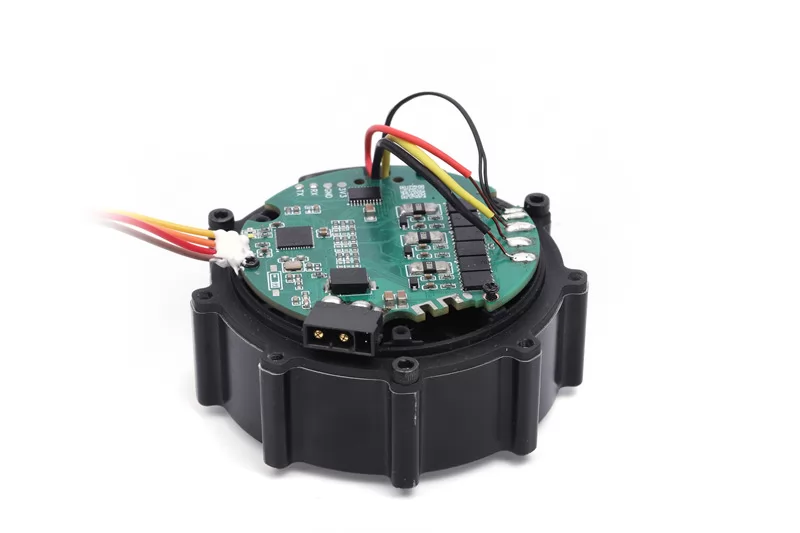
Encoder Integration — The Detail That Gets Overlooked
Most motor suppliers list "encoder compatible" and move on. In practice, encoder integration is where 80% of the commissioning pain happens during a first-time frameless motor integration.
The issue is electrical zero alignment. Your FOC controller needs to know the exact relationship between the rotor's magnetic position and the encoder's zero reference. If this alignment is off by even a few electrical degrees, your torque estimation from motor current — which is how most cobots do joint-level force sensing without a dedicated torque sensor — drifts proportionally.
What we provide to make this work:
Alignment fixtures for each motor platform that allow your assembly team to achieve electrical-zero alignment within ±0.5 electrical degrees. This is the tolerance required for accurate current-based torque estimation.
Validated encoder pairings across three technologies:
- Magnetic absolute encoders (17–22 bit, single-turn) — lowest cost, adequate for most cobot designs. Protocols: BiSS-C, SSI, SPI.
- Optical absolute encoders (21–25 bit, multi-turn) — for premium industrial and medical applications where you need effective resolution above 18 bits.
- Inductive encoders — for harsh-environment installations where magnetic interference or contamination rules out the other two options.
Dual encoder configurations — one encoder on the motor (before the reducer), one on the joint output (after the reducer). This gives you backlash measurement in real time and enables closed-loop torque sensing without a dedicated strain-gauge torque sensor. It adds cost and assembly complexity, but for cobots that need to sense contact forces accurately, the performance improvement over single-encoder estimation is significant.
If your servo driver expects a specific protocol (EnDat 2.2, BiSS-C, Hiperface DSL), send us the driver datasheet. We will confirm compatibility or recommend an encoder that works.
Specifying the Right Motor: The Actual Workflow
The selection flow below is how our engineering team works through a new joint program with a customer. It is also how your team should approach the problem internally before reaching out to any motor supplier.
Step 1 — Define Output Requirements at the Joint
Not at the motor. At the joint output, after the reducer.
- Maximum joint torque under worst-case payload + dynamic loading (include gravity, acceleration, and any external process forces)
- Continuous joint torque under typical duty cycle (this is the number that determines thermal sizing, and it is usually much lower than the peak)
- Maximum joint speed in rad/s
- Required positioning accuracy (arcmin for cobots, arcsec for industrial precision)
- Joint envelope: OD, length, hollow shaft minimum ID
A common mistake at this stage: specifying peak torque based on a dynamic simulation that assumes perfect trajectory tracking, then discovering in real-world testing that the continuous thermal limit — not the peak — is the actual constraint. Size to continuous first.
Step 2 — Select Reduction Ratio
Most cobot arm joints use harmonic reduction between 50:1 and 160:1.
Lower ratios (50:1 to 80:1) give higher output speed and lower reflected inertia at the joint — better for cobots that need fast, responsive motion. The penalty is lower torque multiplication, which means a larger motor for the same output torque.
Higher ratios (100:1 to 160:1) give higher torque density and finer positioning — common in industrial-precision cobots and medical robots. The penalty is higher reflected inertia and lower backdrivability, which matters if your joint needs to be compliant under external force.
Quick calculation: Pre-reduction motor torque ≈ joint output torque ÷ (reduction ratio × 0.8). The 0.8 accounts for harmonic drive efficiency. Use this to bridge between your joint requirement and the motor spec table above.
Step 3 — Match Motor Series
Find the motor series whose continuous torque range covers your pre-reduction requirement with at least 30% margin. Check that peak torque also has margin for acceleration transients. If your requirement falls between two platforms, go with the smaller one and increase the stack length before jumping to the next OD — a longer TS-FM60 is usually a better fit than a shorter TS-FM80 if your joint OD is constrained.
Step 4 — Confirm Electrical Compatibility
Tell us:
- Your servo driver's DC bus voltage
- Driver peak current capability
- Target no-load speed (this determines the winding's KV/KT trade-off)
- Encoder protocol your driver expects
We will return a winding recommendation. Custom windings are standard engineering for OEM programs — there is no catalog-only limitation.
Step 5 — Mechanical Integration
Send your joint cross-section drawing. We return:
- Stator bonding interface tolerances and recommended adhesive
- Rotor bonding interface tolerances
- Bearing selection guidance (the joint integrator typically specifies the cross-roller, but we can recommend based on the load case)
- Magnet temperature rating based on your duty cycle (this determines whether standard N42SH magnets are sufficient or whether you need N38UH for higher thermal margin)
- Cable exit routing options
Integration Example: 6 kg Cobot Wrist Joint
To make the selection process concrete, here is a wrist-3 integration we worked through for a cobot OEM. This is representative of real programs — not a textbook exercise.
Joint requirements:
- 8 Nm continuous, 22 Nm peak at the joint output
- ±0.05° repeatability
- Maximum joint OD: 52 mm (tight — driven by the industrial design team's aesthetic requirements, not the mechanical team's preference)
- Hollow bore: 12 mm minimum for cable routing
Reducer selection: 100:1 harmonic, 0.5 arcmin rated backlash. The customer initially wanted 80:1 for faster wrist reorientation, but the lower ratio would have required stepping up to the TS-FM60 platform to meet the continuous torque requirement — and the TS-FM60's 60 mm stator OD would not fit in the 52 mm joint envelope. The 100:1 ratio kept us on the TS-FM40 platform.
Motor calculation:
- Pre-reduction continuous torque: 8 ÷ (100 × 0.8) = 0.10 Nm
- Pre-reduction peak torque: 22 ÷ (100 × 0.8) = 0.275 Nm
- TS-FM40 with 25 mm stack: 0.4 Nm continuous, 1.5 Nm peak — well within margin on both axes
Encoder configuration: 19-bit magnetic absolute (BiSS-C) on the motor side for FOC commutation, plus 17-bit absolute on the joint output for backlash compensation. The customer evaluated going single-encoder to save cost, but their force-control accuracy requirement (±0.3 Nm at the joint) could not be met without the output-side encoder compensating for harmonic drive transmission error.
Electrical: 48 V DC bus, 6 A peak. Standard winding, no custom needed for this voltage-current envelope.
Result: Joint mass with motor, harmonic, dual encoders, brake, and structure: approximately 720 g. First engineering samples delivered in 5 weeks. Two bonding iterations were needed to nail the stator thermal interface — the customer's initial adhesive layer was too thick, creating a thermal resistance that caused the motor to derate by 15% during extended duty cycles. We resolved this with a thinner bond line and a thermally conductive adhesive recommendation.
This is the kind of engineering support that comes standard on OEM programs. The example is representative — every program has its own constraints and trade-offs.
Can Toosyn Motors Be Used in Humanoid Joints?
Yes, and they already are.
The TS-FM80, TS-FM110, and TS-FM150 are in active use in humanoid arm and torso joint programs. For upper-body joints (shoulder pitch, shoulder roll, elbow), the integration is essentially the same as a cobot — frameless motor plus harmonic reducer.
Humanoid leg joints are a different architecture. Hip and knee joints in walking humanoids need backdrivability for impact absorption, which means low-ratio planetary reduction (6:1 to 10:1) instead of harmonic. The resulting actuator is a QDD (quasi-direct-drive) design. We supply both the frameless motor and integration guidance for QDD builds — the motor's low cogging is particularly important here because there is no high-ratio gearbox to mask it.
For humanoid hand and finger actuators — a rapidly growing application area — we have developed compact motor platforms outside the standard series. Contact our engineering team if this is relevant to your program.
Quality, Certification, and Supply
- IATF 16949 — automotive quality management, with lot traceability and SPC
- ISO 14001 — environmental management
- REACH and RoHS compliant
- PPAP capability for production programs
Volume range: Development batches from 50 units through production volumes of 100,000+ units annually.
Lead times: Engineering samples in 4–6 weeks. Production in 8–12 weeks depending on volume and customization. These are real lead times — not the optimistic numbers that get adjusted after you place the PO.
Send Us Your Joint Spec
For a technical proposal, we need the following minimum information:
- Robot type and target application
- Joint position(s) you are sourcing for
- Required output torque — continuous and peak — at the joint
- Required output speed and positioning accuracy
- Joint envelope constraints (OD, length, hollow shaft ID)
- Target annual volume
- Program timeline
Country, company, and engineering contact are required — our team needs to route inquiries by region and verify export-compliance obligations.
We respond to qualified technical inquiries within two business days with an initial motor recommendation, an indicative datasheet, and a sample-program proposal.
Submit Your Technical Inquiry →
0
Comments
Leave a Comment
Your email address will not be published. Required fields are marked *
Name can't be empty
Email error!
Message can't be empty
😍
😜
😳
😌
😄
😘
😝
😒
😃
😚
😚
😛
😟
😧
😀
😉
😓
😱
😤
😣
😂
😥
😩
😠
😢
😭
😰
😨
😡
😆
😪
😅
😐
😇
😋
😴
👿
😕
😏
😷
😵
😟
😮
😯
😑
👧
👴
😧
😬
😾
👶
👱
👵
👸
🙀
👺
👦
👩
👨
😽
😿
🙈
💩
💥
💤
😼
😹
🙉
🔥
✨
💦
👎
✌
👆
👈
💪
💹
👍
👊
💴
💶
💷
💸
👉
💵
🙏
🌎
🏧
👏
💳
👇
💑
🙆
🙅
💁
👫
👭
🙎
🙇
👑
👔
Submit Comment
Most Popular
-
 Aug 21, 2025Which Motor Is Best for Electric Vehicle? A Complete Guide for 2026
 -
 Oct 16, 2025Top 10 DC Motor Manufacturers in China 2026
 -
 Dec 18, 2025The Ultimate Buyer's Guide to High Torque DC Motors
 -
 Apr 11, 2026Top 10 China Gear Motor Manufacturer in 2026


Laster Blogs
-
 Aug 20, 2026Why Planetary Gear Motors Offer Low Backlash for Precision Positioning
 -
 Aug 19, 2026Planetary Gear Ratio Calculation: How to Calculate the Right Gear Ratio for Your Motor
 -
 Aug 18, 2026Planetary Gearbox vs Spur Gearbox: Why Planetary Wins in Compact High-Torque Applications
 -
 Aug 17, 2026What Is a Planetary DC Gear Motor and How Does It Work?


Set A Consultation Today
Name can't be empty
Email error!
Send Your Message
*We respect your confidentiality and all
information are protected.


