Why Planetary Gear Motors Offer Low Backlash for Precision Positioning
Aug 20, 2026
Toosyn
_1787217716_WNo_1600d900.webp)
In our guide on planetary gear ratio calculation, we covered how to match a motor's speed and torque to your load through the gearbox. But gear ratio answers only one question: how far does the output turn? In precision positioning systems, a second question matters just as much — how faithfully does the output follow the input when the direction of motion changes? That question leads directly to backlash.
Backlash — the angular clearance inside a gearbox that appears as lost motion on direction reversal — affects positioning accuracy, repeatability, servo response, and dynamic behavior in robotics, automation, CNC, and motion-control systems. This guide explains what backlash is, where it comes from in a planetary gearbox, why the planetary architecture supports low-backlash designs, how backlash interacts with encoder feedback, and how to select a low-backlash gear motor for your application.
One point of precision before we begin: planetary gear motors do not have low backlash automatically. Low backlash is a design and manufacturing achievement — controlled gear clearance, accurately machined components, quality bearings, and careful assembly. What the planetary layout provides is an architecture in which that precision is achievable in a compact, rigid, inline package. This guide explains both sides of that statement.
What Is Backlash in a Gear Motor?
Backlash is the angular clearance — the free play — inside a gear train, observed as lost motion when the direction of torque transmission changes. While torque flows in one direction, the driving gear teeth press against the driven flanks and the transmission is loaded. The moment the motor reverses, the driving teeth separate from the flanks they were pushing, rotate through the intervening clearance, and only then re-engage on the opposite tooth flanks. During that interval, the input shaft is turning and the output shaft is not.
Backlash is a system property, not the property of a single component. It accumulates from several mechanical sources:
Gear Tooth Clearance
Gears cannot be manufactured and operated with zero clearance between mating teeth. A controlled amount of space between tooth flanks is required for lubricant film, thermal expansion, and smooth engagement. The clearances across all meshing teeth in the transmission path contribute directly to total backlash.
Bearing Clearance
The shafts inside a gearbox are supported by bearings, and bearings have internal radial and axial play. This play allows the shafts — and the gears mounted on them — to shift slightly whenever the load direction changes, adding to the free angular movement at the output.
Shaft and Carrier Clearance
In planetary gearboxes specifically, the planet carrier, planet pins, and floating members carry fit tolerances. Small clearances between these components allow the planets to shift slightly relative to the sun gear and ring gear, which appears as additional lost motion at the output.
Manufacturing Tolerances
Every gear carries machining errors — tooth profile deviation, pitch error, runout, and eccentricity. Every housing carries bore-position and center-distance tolerances. These deviations combine statistically through the transmission and manifest as backlash and transmission error.
Assembly Tolerances
How accurately components are aligned, preloaded, and fastened during assembly further changes the realized clearance. Two gearboxes built from identical parts can exhibit different backlash if assembled to different standards.
Wear Over Time
Backlash is not constant over the life of the gearbox. Tooth flank wear, bearing wear, and surface fatigue gradually increase clearances — which is why backlash specifications apply to a gearbox in its delivered condition, and why service history matters when evaluating equipment.
Backlash and lost motion are closely related terms. Backlash describes the clearance inside the drive; lost motion describes the observable result — the angular movement at the input that produces no movement at the output during reversal. Because the two are linked but not identical, manufacturers sometimes specify one or the other, and the definitions must be checked before comparing products. Backlash is most commonly expressed in angular units — arcminutes (arcmin), where one degree equals sixty arcminutes — though degrees and milliradians also appear.
Finally, it must be stressed: backlash is not a manufacturing defect. Some clearance is essential for lubrication, thermal expansion, manufacturing tolerance, and dependable tooth engagement. A gearbox built with zero effective clearance would tend toward binding, friction, heat, and accelerated wear. The engineering goal is not to eliminate backlash, but to control it to a level appropriate for the application — the subject of the rest of this guide.
Why Does Backlash Matter for Precision Positioning?
In drives that always turn one direction, backlash is largely invisible: the teeth stay loaded on one flank and the output tracks the input continuously. Precision positioning systems are rarely that simple. Robots, CNC axes, indexing tables, camera gimbals, and automated stages constantly reverse direction to reach targets from both sides — and on every reversal, the gearbox must first take up its backlash before the output moves. That is where backlash becomes a performance parameter.
Positioning Accuracy
Positioning accuracy is the closeness of the actual output position to the commanded position. When the direction of approach reverses, backlash appears directly as angular error at the output: the controller believes the axis has arrived — the motor shaft and its encoder have, in fact, reached the commanded angle — but the load is short of the target by the amount of lost motion. The larger the backlash, the larger this reversal error.
Repeatability
Repeatability is the scatter of positions achieved when the same target is commanded repeatedly. Backlash degrades bidirectional repeatability because the same target approached from opposite directions stops at different points: on one approach the teeth are loaded on one flank; on the other, the clearance must first be traversed. A system can be highly repeatable in unidirectional operation yet scatter significantly in bidirectional operation — a distinction that matters when writing and interpreting test specifications.
Direction Reversal
The mechanism is worth stating explicitly, because it explains every downstream effect. On reversal, the motor and input gears reverse and rotate through the internal clearance. The encoder — typically mounted on the motor — begins reporting movement immediately. The output shaft remains stationary until the clearance is fully taken up and the opposite tooth flanks engage. Only then does the load respond. Under fast, loaded reversals, this re-engagement can occur with an impact rather than a smooth transfer of load.
Servo Response
Backlash introduces a dead band into the control loop. Within the backlash zone, motor movement produces no output movement, so the plant response lags the commanded motion. Control loops must be tuned to cope with this nonlinearity: aggressive tuning can produce oscillation or hunting around a reversal point, while conservative tuning slows settling. Frequent small reversals near a target are the classic worst case for backlash-limited servo systems.
Vibration and Noise
When a gearbox reverses under load at speed, tooth flanks separate and re-engage, and the energy of re-engagement can excite vibration and mechanical noise. In machinery with high reversal frequency, backlash contributes measurably to impact loading on gear teeth, structure-borne noise, and fatigue over time.
It is worth keeping three terms distinct. Backlash is a mechanical property of the gearbox — the internal clearance. Positioning error is a system outcome — the difference between commanded and actual position. Repeatability is a statistical measure — the scatter of achieved positions. Backlash is one contributor to positioning error and a major cause of bidirectional repeatability loss, but it is never the only one.
| Engineering Note Low backlash does not guarantee high positioning accuracy. Final positioning performance also depends on encoder resolution and location, control algorithms, coupling compliance, mechanical stiffness, load conditions, and thermal effects. A low-backlash gearbox in a compliant, poorly controlled system will still position poorly. |
Why Can Planetary Gear Motors Achieve Low Backlash?
Planetary gear motors have a strong association with precision motion, and the reason is architectural: the epicyclic layout offers characteristics that make low-backlash designs achievable in a compact package. But the statement must be made correctly — planetary gearboxes can be designed and manufactured for low backlash. Low backlash is not an automatic property of the planetary label; it results from design decisions and manufacturing quality applied to that architecture.
Multiple Gear Engagement
In a planetary gearbox, torque flows from the sun gear to multiple planet gears simultaneously, and from the planets into the ring gear. The load is shared across several gear meshes rather than concentrated in one. This load sharing allows each mesh to be engineered with tighter, better-controlled clearance while still carrying the transmitted torque, and the symmetric distribution of load helps maintain consistent mesh conditions during operation.
Concentric Architecture
The sun gear, planet gears, ring gear, and carrier all operate on a single common axis, with input and output inline. This concentric arrangement balances radial forces internally — the planets' reactions largely cancel around the ring — which reduces bending loads on shafts and housings, supports a compact and rigid structure, and provides stable geometry for the gear meshes. Structural rigidity and symmetry are prerequisites for holding a specified clearance under load.
Controlled Gear Tooth Clearance
Because the planetary layout distributes load, manufacturers can machine gears to higher accuracy — precision-cut or ground teeth with controlled profile and pitch — and manage center distances tightly, targeting a specified clearance rather than accepting whatever the tolerance chain delivers. Selective assembly and matched component sets are additional tools for hitting a backlash target.
Precision Carrier and Bearings
The planet carrier holds the planets in their precise positions relative to sun and ring, and carrier accuracy is critical: carrier runout or deflection shifts the planets and varies the effective mesh clearance as the gearbox rotates. Low-backlash planetary designs therefore use rigid, accurately machined carriers and quality bearings to limit the radial and axial play of the sun, planets, and output shaft.
Manufacturing and Assembly Accuracy
The final backlash specification of a planetary gearbox is the outcome of the entire production chain — gear machining accuracy, housing bore precision, bearing selection, carrier machining, and assembly alignment — across every stage in the gearbox. This is also why the number of stages matters: each additional stage adds gear meshes and tolerance contributions that must be engineered and controlled.
| Engineering Note Architecture alone does not decide backlash. A precision-ground helical gearbox or a well-made worm set can achieve very low backlash; a loosely manufactured planetary gearbox will not. Two "planetary" gearboxes of the same size and ratio can differ substantially in backlash. Compare specified values under comparable measurement conditions — not architecture labels. |
Where Does Backlash Come From in a Planetary Gearbox?
Because backlash in a planetary gearbox is a system-level result, it helps to map every contributing source explicitly:
| Source | Effect on the Output |
|---|---|
| Gear tooth clearance | Angular play at each mesh |
| Sun–planet mesh | Transmission error, lost motion |
| Planet–ring mesh | Output precision impact |
| Planet carrier | Output movement and runout |
| Bearings | Radial and angular play |
| Assembly tolerance | Accumulated error |
| Wear | Gradually increasing backlash |
Sun–Planet Gear Clearance
The sun–planet mesh is the primary torque input path. Clearance between the sun teeth and planet teeth — from tooth design, machining accuracy, and center-distance tolerance — contributes directly to lost motion. Eccentricity of either gear adds a rotating component that modulates the effective clearance through every revolution.
Planet–Ring Gear Clearance
Each planet also meshes with the fixed internal ring gear. Clearance in this mesh affects how precisely the planet's rotation is transferred to the carrier, and therefore to the output. Because the ring gear is internal, its accuracy — profile, runout, and roundness — directly shapes the planet's orbital motion.
Planet Carrier
The carrier converts the planets' orbital motion into output shaft rotation. Carrier machining errors (pin position and runout) and deflection under load shift the planets relative to sun and ring, producing both backlash and transmission error at the output.
Bearing Clearance
Radial and axial play in the bearings supporting the sun (where floating), the planet pins, and the output shaft allows small position shifts of the gears themselves. This play is added to the free angular movement whenever the load direction changes.
Manufacturing Tolerances
Tooth profile error, pitch error, runout, eccentricity, bore position, and center-distance tolerances stack statistically through the gearbox. Tolerance stack-up is the reason two gearboxes of the same design can exhibit different backlash — and why manufacturing discipline is inseparable from backlash performance.
Assembly Tolerances
Component alignment, preload settings, fastening, and cleanliness during assembly all shift the realized clearance. Assembly is the last — and frequently underestimated — contributor to backlash.
Wear
Surface wear on tooth flanks, pins, and bearings increases clearances progressively over service life. A gearbox's backlash at delivery and after years of duty are different numbers; lubrication quality and load history govern the difference.
The essential point: backlash is not the result of one gear pair alone. Sun–planet clearance, planet–ring clearance, carrier accuracy, bearing play, machining tolerances, assembly, and wear all combine. And in a multi-stage planetary gearbox, the contributions of individual stages do not reach the output equally — the stage closest to the output tends to dominate the backlash observed at the output shaft, because its clearances act directly on the output, while the influence of stages nearer the input is reduced by the intervening gear ratios. This is why precision multi-stage designs — and position-sensing arrangements built onto gear trains — give the output-side stage the most design and manufacturing attention.
How Is Planetary Gearbox Backlash Measured?
Arcminutes
Backlash is an angular quantity, and the standard unit in gearbox specifications is the arcminute (arcmin):
1° = 60 arcmin → 1 arcmin = 1/60° ≈ 0.0167°
For quick orientation: 3 arcmin = 0.05°, 6 arcmin = 0.1°, and 15 arcmin = 0.25°. A gearbox specified at 6 arcmin of backlash therefore exhibits one tenth of a degree of free angular movement at the output on reversal.
Lost Motion
Some manufacturers specify lost motion instead of, or alongside, backlash. Lost motion is the measured angular lag between input and output on reversal, and can include elastic deflection under the measurement load in addition to pure clearance. A lost-motion figure and a backlash figure are not automatically interchangeable — always check which quantity a datasheet reports.
Direction Reversal Testing
The measurement principle is conceptually simple: lock or load the output, reverse the input through a defined angle under defined conditions, and measure the angular difference. In practice, the result depends on the measurement load (a light-load test can miss clearances that close under torque), the temperature, the gear position (backlash varies around one revolution due to runout and eccentricity, so many specifications represent a maximum or statistical value), and the exact definition the manufacturer applies.
Consequently, two published backlash numbers are comparable only when their measurement conditions and definitions are comparable. When backlash is critical to your application, ask the manufacturer for the basis behind the figure: measurement load, temperature, whether the value is typical, average, or maximum, and at which point in the transmission the value is referenced.
It also follows that "zero backlash" is generally not a meaningful practical target for a conventional gearbox: some clearance is required for lubrication, thermal expansion, manufacturing tolerance, and reliable operation. The next section examines why.
| Engineering Note Never compare backlash specifications across brands without checking measurement conditions. Test load, temperature, gear position, and the definition of the quoted value (typical, average, or maximum) all change the number. A lower advertised arcminute figure is not automatically a tighter gearbox. |
Low Backlash vs Zero Backlash: What Is the Difference?
Why not simply eliminate backlash altogether? Because clearance is not a parasite — it is a working requirement. Gear teeth need space for the lubricant film. Housings and gears expand and contract with temperature; a clearance that is "zero" at 20 °C can become negative at operating temperature. Bearings need internal play to roll rather than skid. A gearbox engineered toward zero effective clearance tends toward binding, elevated friction and heat, accelerated wear, rough rotation, and sensitivity to manufacturing variation.
Research on low-backlash planetary designs reflects the same trade-off: reducing backlash involves balancing load distribution, component eccentricity, and assembly conditions against smooth operation — tightening clearance in one dimension can degrade behavior in another. Backlash, friction, heat, lubrication, wear, thermal expansion, and rotation smoothness must be optimized together, not minimized one at a time.
In practice, the appropriate backlash target is defined by the application: the positioning accuracy actually required, the load, the speed, the duty cycle and reversal frequency, and the environmental temperature range. A laboratory positioning stage, a robot joint, and a packaging indexer have completely different "correct" backlash values. No universal arcminute number suits all applications, and a specification tighter than the application needs usually costs money, efficiency, or service life without benefit.
| Engineering Note Zero backlash is not automatically the better gearbox. Gears require controlled clearance for lubrication, thermal expansion, and reliable operation. Specifying backlash tighter than the application requires trades friction, heat, wear, and cost for accuracy the system cannot use. Define the backlash target from the application, not from the smallest number on the market. |
How Does Backlash Affect an Encoder-Based Positioning System?
The interaction between backlash and encoder feedback is one of the most misunderstood topics in precision motion, so it deserves a careful look. Consider a typical encoder-equipped gear motor driving a positioning load:
		Motor Shaft
			|
			v
	  [ Encoder ]        <- motor-side feedback: precise motor angle
			|
			v
   Planetary Gearbox      <- ratio + backlash live here
			|
			v
	   Output Shaft
			|
			v
		  Load            <- load-side position: what actually matters
   Forward stroke:  input ------------------>   output follows
   Reverse stroke:  input <--[ BACKLASH ]<--    output waits (lost motion)
Three different "positions" exist in this chain:
- The motor shaft position — where the encoder typically measures.
- The gearbox output shaft position — after the planetary reduction and its backlash.
- The actual load position — after any couplings, belts, or compliance between output and load.
An encoder, no matter how high its resolution, reports position #1. It can be excellent at that job — resolving the motor's angle to a fraction of a degree — while the gearbox output still lags during reversal, because the motor's rotation is first consumed by taking up the gearbox's internal clearance. In that moment, the encoder confirms that the motor has reversed, while the output has not moved at all. Motor feedback accuracy and output positioning accuracy are not the same thing.
This is why a high-resolution encoder does not automatically eliminate mechanical backlash: the encoder measures rotation, but it does not change the mechanics between its mounting point and the load. What feedback can do is make backlash manageable — the control system can be programmed to compensate for the dead band, for example by always approaching targets from one direction or by applying reversal offsets.
Where the application justifies it, engineers go further:
- Output-side feedback (dual-loop control): a second encoder measures the output or load directly, closing the position loop after the gearbox so lost motion is observed rather than assumed.
- Low-backlash gearing: reducing the mechanical clearance itself, so that less lost motion exists to compensate.
- Mechanical stiffness: stiff couplings and structures ensure that what movement the output makes reaches the load without additional compliance error.
Used together, these measures can deliver excellent positioning performance — but the mechanical backlash itself is only addressed by the mechanics, never by the feedback electronics alone.
Toosyn offers magnetic encoder for position feedback options designed for exactly this class of motor-side feedback in positioning applications.
How Gear Ratio and Number of Stages Affect Backlash
A common assumption is that a higher gear ratio means higher backlash. The reality is more nuanced — and understanding it requires separating ratio from stages.
Gear ratio and backlash are not directly coupled. A single planetary stage is practically limited to roughly 10:1 reduction, so higher ratios are achieved by stacking stages — and it is the number of stages, not the ratio number itself, that changes the backlash picture. A high-ratio design executed in one well-controlled stage architecture does not automatically carry more backlash than a low-ratio one.
What changes with stages: each additional stage introduces another set of gear meshes, bearings, carriers, and tolerance stack-ups. Every one of those elements carries clearance that can appear at the output. The engineering consequence is that backlash must be managed at every stage, and multi-stage gearboxes demand tighter manufacturing control to hold a given output backlash specification.
Where the stage sits matters. The stage closest to the output acts directly on the output shaft, so its clearances appear essentially one-to-one in the output lost motion. The influence of stages nearer the input is reduced by the gear ratios between those stages and the output. In precision multi-stage designs and in position-sensing arrangements built onto gear trains, the output-side stage therefore receives the most design attention.
Ratio selection also interacts with positioning in a second way: a higher ratio reduces the load inertia reflected to the motor and increases output torque per motor amp, but it also places more gearbox between the motor encoder and the load — reinforcing the value of low-backlash, high-accuracy stages in precision systems.
For the complete ratio-selection picture — how to compute the ratio your application needs from motor speed and required output speed, and how multi-stage ratios combine — see our guide on planetary gear ratio calculation.
How to Choose a Low Backlash Gear Motor for Precision Positioning
Selecting a low-backlash gear motor for precision positioning is a system exercise, not a catalog search for the smallest arcminute number. The following sequence keeps the decision anchored to the application:
| # | Step | What to Define |
|---|---|---|
| 1 | Define positioning accuracy | Required accuracy at the load — angular (arcmin/degrees) or linear (mm) at the working radius |
| 2 | Determine acceptable backlash | Convert the accuracy budget into a gearbox backlash specification, leaving allowance for other error sources |
| 3 | Determine output torque | Continuous and peak torque at the output, with margin for duty and impact loads |
| 4 | Determine output speed | Operating speed range, including reversal frequency and settling requirements |
| 5 | Check gear ratio | Ratio between motor and output, and how many stages it implies |
| 6 | Evaluate encoder resolution | Resolution at the motor, effective resolution at the output after the ratio, and feedback architecture (single vs. dual loop) |
| 7 | Check radial and axial loads | Output shaft bearing limits versus loads from pulleys, gears, or cantilevered arms |
| 8 | Verify duty cycle | Thermal duty, reversal frequency, and duty profile over a representative shift |
| 9 | Compare measurement conditions | Ask each manufacturer how their backlash figure is defined, measured, and loaded |
| 10 | Validate the complete motion system | Motor + gearbox + coupling + load + controller tested together against the accuracy target |
| Procurement Note Don't select a gearbox solely because it has the smallest advertised backlash number. That number may be measured under different conditions, may not represent maximum values over the full revolution, and may buy precision the rest of the system cannot use. Backlash interacts with encoder resolution, coupling stiffness, load inertia, control strategy, and mechanical tolerances — the best number on paper is not always the gearbox that positions best in your machine. |
The last step deserves emphasis: a gear motor should be validated as part of the complete motion system — motor, gearbox, coupling, load, and controller — against the application's accuracy and repeatability targets, under realistic load and reversal conditions. Isolating any one component, including the gearbox, tells you less than testing the system it will live in.
Planetary Gear Motor vs Other Gearbox Types for Precision Positioning
How does the planetary gearbox compare against other common gear motor architectures for precision positioning? The honest answer is that backlash performance depends on design and manufacturing quality within any architecture — but the architectures differ in what they make easy:
| Factor | Planetary | Spur | Worm | Precision Helical |
|---|---|---|---|---|
| Torque Density | High | Moderate | High | High |
| Compactness | High | Good | Moderate | Moderate |
| Backlash Potential | Low-backlash designs available | Design dependent | Design dependent | Low-backlash designs available |
| Positioning | Excellent when properly specified | Application dependent | Application dependent | Excellent |
| Efficiency | Generally high | High | Often lower | High |
| Encoder Integration | Easy | Easy | Easy | Easy |
Note what the table does not say: that planetary gearboxes always have the lowest backlash. A precision helical gearbox from a quality manufacturer can match or beat a mediocre planetary; a well-made worm gearbox can achieve low backlash when optimized for it. Backlash correlates with tooth profile quality, gearhead design, and manufacturing discipline — architecture sets the possibilities; execution decides the outcome. Choose candidates by specification and measurement conditions, then verify.
Backlash Calculation Example: From Arcminutes to Linear Position Error
A small calculation makes arcminute specifications tangible. Consider a gearbox with 5 arcmin of backlash driving an arm with a 100 mm radius — a robot link, a camera lever, or an indexing crank. How far does the end of the arm theoretically "float" when the direction reverses?
Step 1 — Convert arcminutes to degrees:
5 arcmin × (1° / 60 arcmin) = 5/60° = 0.0833°
Step 2 — Convert degrees to radians:
0.0833° × (π / 180°) ≈ 0.001454 rad
Step 3 — Apply s = r × θ:
s = 100 mm × 0.001454 rad ≈ 0.145 mm
The answer: approximately 0.145 mm of theoretical lost motion at the end of the arm, per reversal. This single number explains why arcminute-level backlash matters — five arcminutes, a twelfth of a degree, becomes nearly a sixth of a millimeter at a 100 mm radius before any other error source contributes.
Two cautions apply. First, this is an ideal geometric example: it assumes a rigid arm, a perfect pivot, and backlash as the only error source. Real systems add load-dependent compliance, coupling flexibility, bearing clearance, encoder location effects, and control behavior, so actual positioning error is usually larger than the backlash term alone. Second, backlash is not the only source of positioning error — it is one contributor among several, and its importance rises with reversal frequency and the precision demanded of the mechanism.
Toosyn Low-Backlash Planetary Gear Motor Options
Toosyn manufactures a range of planetary DC gear motors engineered for compact precision motion, including series the manufacturer specifies with minimum backlash characteristics and integrated feedback options. Three series are particularly relevant to low-backlash positioning applications:
PG28395 Series — 28 mm Planetary Gear Motor with Encoder
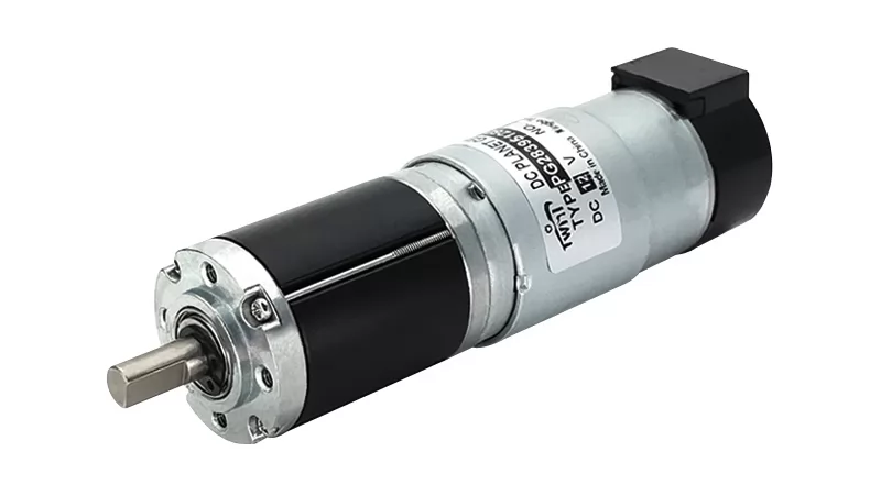 |
PG28395 Series — 28 mm Planetary Gear Motor with Encoder
A compact precision option for space-constrained positioning axes. The PG28395 combines a 28 mm planetary gearbox with an integrated encoder, in a high-precision, positioning-oriented design.
|
PG36555 Series — 36 mm Planetary Gear Motor with Encoder
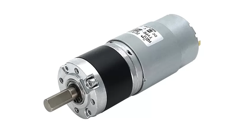 |
PG36555 Series — 36 mm Planetary Gear Motor with Encoder
A compact-to-mid power low-backlash planetary gear motor for positioning applications. The manufacturer specifies minimum backlash for the series.
|
PG56ZY58 Series — 56 mm Planetary Gear Motor with Encoder and Brake
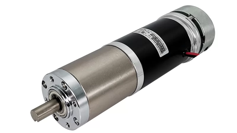 |
PG56ZY58 Series — 56 mm Planetary Gear Motor with Encoder and Brake
A higher-power planetary gear motor with encoder and brake for precision systems that need holding torque as well as position feedback. The manufacturer specifies minimum backlash for the series.
|
The three series at a glance:
| Series | Diameter | Power | Encoder | Typical Positioning Focus |
|---|---|---|---|---|
| PG28395 | 28 mm | 3–11 W | Yes | Compact precision applications |
| PG36555 | 36 mm | 4–20 W | Available | Low-backlash applications |
| PG56ZY58 | 56 mm | 30–100 W | Yes | Higher-power precision systems |
Comparing the series: engineers typically start from output torque and size — PG28395 for compact axes, PG36555 for compact-to-mid loads, PG56ZY58 where tens of watts and a holding brake are needed — then confirm the feedback architecture, then match ratio and speed to the application. For each candidate, request the backlash specification and its measurement basis, and validate the final selection against the actual load, output speed, duty cycle, positioning accuracy, and installation requirements — not the datasheet alone.
Frequently Asked Questions
What is backlash in a planetary gear motor?
Backlash is the angular clearance, or "lost motion," inside a gearbox that appears when the direction of torque transmission reverses. Before the output shaft follows the input, the drive must first take up the free play between gear teeth, bearings, and carrier components. It is specified in angular units — most commonly arcminutes — and is a normal feature of gear systems rather than a defect.
Why is low backlash important for precision positioning?
In bidirectional positioning systems, the motor must take up gearbox backlash every time direction reverses. Higher backlash therefore appears as output angular error, degraded repeatability, delayed servo response, and in some cases vibration or noise on reversal. Low backlash reduces this lost motion so the output tracks commanded positions more closely — which matters in robotics, CNC, and automated motion-control applications.
Do planetary gear motors have less backlash?
Not automatically. Planetary architecture supports low-backlash designs because torque is shared across multiple gear meshes in a concentric layout, but the final backlash depends on gear machining accuracy, tooth clearance, bearings, carrier precision, assembly quality, and the number of stages. A well-made planetary gearbox can achieve very low backlash; a poorly made one will not, regardless of architecture.
What causes backlash in a planetary gearbox?
Contributors include clearance in the sun–planet and planet–ring gear meshes, planet carrier movement, bearing clearance, output shaft play, gear machining errors, tolerance stack-up across manufacturing and assembly, and progressive wear in service. Backlash is a system-level result of all these elements combined — which is why it must be engineered and measured rather than assumed from any single component.
How is planetary gearbox backlash measured?
Backlash is typically measured as the angular difference between input and output when the input direction is reversed under defined conditions, expressed in arcminutes, where one degree equals sixty arcminutes. Because manufacturers may apply different measurement loads, temperatures, and definitions, published values should only be compared when the measurement conditions are comparable. Always request the measurement basis behind a specification.
What is a good backlash value for a precision gear motor?
There is no universally "good" value — the right backlash depends on the positioning accuracy the application requires, along with load, speed, reversal frequency, and duty cycle. A packaging conveyor tolerates far more backlash than a robot joint. Define the acceptable output angular error first, then translate it into a gearbox backlash specification and verify the measurement conditions behind it.
Does a higher gear ratio increase backlash?
Not automatically — backlash at the output is not a simple function of ratio. However, achieving a high ratio usually requires multiple stages, and each additional stage adds gear meshes, bearings, and tolerances whose effects accumulate toward the output. The stage closest to the output tends to influence final lost motion most, so multi-stage designs demand tighter manufacturing control.
Can an encoder compensate for gearbox backlash?
An encoder improves control but does not remove mechanical backlash. If the encoder is on the motor side, it reports motor rotation precisely while the gearbox output may still lag during reversal — feedback accuracy is not the same as output positioning accuracy. Low-backlash gearing, adequate stiffness, output-side feedback, and control strategies such as directional compensation all help, but none physically eliminates backlash.
What is the difference between backlash and lost motion?
Backlash is the designed and accumulated angular clearance inside the gearing — the free play between components. Lost motion is the observable result: the output movement that fails to appear when the input reverses, before the clearance is taken up. Lost motion can also include deflection under load, so it is usually the broader, system-level term.
Which planetary gear motor is best for precision positioning?
No single model is universally best. Selection depends on output torque and speed, the backlash specification the application can tolerate, feedback requirements, available space, duty cycle, and load inertia. A compact encoder motor may suit a small positioning axis, while higher-torque systems may need an encoder-plus-brake configuration. Validate the complete motor–gearbox–load system before finalizing the choice.
Backlash will never be eliminated from geared motion — and as this guide has shown, it should not be. What precision systems need is backlash that is specified, measured, and controlled to a level the application actually requires, inside an architecture — like the planetary gearbox — that makes such control achievable. For help matching a low-backlash planetary gear motor to your positioning application, talk to our engineering team.
|
Need a low-backlash planetary gear motor for your precision positioning application? Send us your requirements — output torque, speed, ratio, feedback needs, and acceptable backlash — and our engineers will help you match the right PG series motor to your system. Request a QuoteExplore our planetary DC gear motors · Learn more about encoders and brakes |
0
Comments
Leave a Comment
Your email address will not be published. Required fields are marked *
Name can't be empty
Email error!
Message can't be empty
😍
😜
😳
😌
😄
😘
😝
😒
😃
😚
😚
😛
😟
😧
😀
😉
😓
😱
😤
😣
😂
😥
😩
😠
😢
😭
😰
😨
😡
😆
😪
😅
😐
😇
😋
😴
👿
😕
😏
😷
😵
😟
😮
😯
😑
👧
👴
😧
😬
😾
👶
👱
👵
👸
🙀
👺
👦
👩
👨
😽
😿
🙈
💩
💥
💤
😼
😹
🙉
🔥
✨
💦
👎
✌
👆
👈
💪
💹
👍
👊
💴
💶
💷
💸
👉
💵
🙏
🌎
🏧
👏
💳
👇
💑
🙆
🙅
💁
👫
👭
🙎
🙇
👑
👔
Submit Comment
Most Popular
-
 Aug 21, 2025Which Motor Is Best for Electric Vehicle? A Complete Guide for 2026
 -
 Oct 16, 2025Top 10 DC Motor Manufacturers in China 2026
 -
 Dec 18, 2025The Ultimate Buyer's Guide to High Torque DC Motors
 -
 Apr 11, 2026Top 10 China Gear Motor Manufacturer in 2026


Laster Blogs
-
 Aug 20, 2026Why Planetary Gear Motors Offer Low Backlash for Precision Positioning
 -
 Aug 19, 2026Planetary Gear Ratio Calculation: How to Calculate the Right Gear Ratio for Your Motor
 -
 Aug 18, 2026Planetary Gearbox vs Spur Gearbox: Why Planetary Wins in Compact High-Torque Applications
 -
 Aug 17, 2026What Is a Planetary DC Gear Motor and How Does It Work?


Set A Consultation Today
Name can't be empty
Email error!
Send Your Message
*We respect your confidentiality and all
information are protected.


